Page last updated on July 17, 2026 at 7:54 am
PLAN SUBMISSION GUIDELINES:
CBU requires digital submission of plans (PDF files or file-share links) for all project reviews along with our Plan Review Application as part of your initial submission.
- New Construction: Plan Review Application - New Development
- Existing Location - Remodel / Renovation: Plan Review Application - Remodels
Email the appropriate form and plans to our Plan Review Team at: [email protected]. Refer to the complete list of required items under the PLAN SUBMISSION Section of our Design Standards Manual & Project Review Guidelines. If your project requires plumbing and/or landscaping plans, please refer to those sections as well.
DESIGN STANDARDS & REVIEW GUIDELINES
This Design Standards Manual has been developed for use by engineers, consultants and developers working on water, sanitary, and stormwater utility projects within the City of Bloomington Utilities’ (CBU) jurisdiction in Bloomington, Indiana; and should be used in conjunction with the current issue of Construction Specifications for City of Bloomington Utilities. This manual does not constitute a complete list of design criteria, but is to be used as a guide that will provide conformity to the design and plan review process. These Standards are not intended to replace sound engineering judgment nor any applicable standards of practice, permits, laws, or rules and regulations enforced by local, state, or federal guidelines. Designers should consider the applicability of the contents of this document to specific projects and, based on the characteristics and requirements of the projects, make adjustments accordingly.
The sections of this manual identify routine or standard design assumptions and practices used and accepted by this Department. Deviations from these Standards, and special or unique design situations should be thoroughly addressed in writing to the Utilities Engineer for acceptance and approval during the plan review process.
Each of the items listed within this manual may or may not be individually addressed in plan review correspondence to the engineer or consultant, but all guidelines applicable to a project will be required to be met prior to Final Acceptance and Approval of the plan design.
PLAN SUBMISSION REQUIREMENTS:
CBU requires a digital pdf copy of the plans to be submitted for review for all projects. Please complete the appropriate Plan Review Application (links at the top of this page) and include it with your initial plan submission. Email your plans, review application, and any additional documentation to: [email protected].
Additional information and forms are available on our website at: www.bloomington.in.gov/utilities/review
Initial Submittal:
Complete the Utility Plan Review Application (available in our Forms & FAQ section of the website) and include it with your first plan submittal to our office.
Preliminary Design Submittals:
If you are submitting plans to satisfy another department’s requirements, and are not prepared for a full plan review, make notations as such on your Utility Plan Review Application form along with any additional information that will identify the level of review required at this time.
Review Teams:
CBU will assign a group of team members to each project based upon the items involved with it. Most projects will include a primary Project Reviewer, but may also include any, or all, of the following staff members: Engineer, Backflow Reviewer, Pretreatment Reviewer, Landscaping & Easement Reviewer, MS4/SWPPP/CSGP Reviewer, and Fireline/New Services Reviewer.
Project Review Timelines:
Plans are reviewed based upon the date of submission. CBU aims to maintain a standard review timeline of 2-4 weeks to allow for all parties to have adequate time to review their portion of the project. This timeline will not be adjusted to accommodate requests for a full review to be expedited. Immediate reviews of a minor revision for correctness are at the discretion of the Project Reviewer. CBU reserves the right to refuse further review of plans not containing the requested revisions, requested documents, or issues being adequately addressed in writing. CBU will not accept additional plan documents or partial revisions while an existing review is underway. Please provide all necessary documents in a single submission.
Construction Plans are to Include:
- Preferred sheet size: 24” x 36”, and are to be drawn to scale
- Title page with official Project Name, Site Address, Owner/Developer Contact Information, Index, and Location Maps
- Project Name, Page Numbers, North Arrow (on all applicable sheets), and Firm's Project #
- Demo Plan (if applicable)
- Scaled Site Plan, Applicable Utility Notes, Easements (existing & proposed), and Summary Chart or Note for the Total Pervious & Impervious Areas
- Utility Plan & Profiles, All Existing & Proposed Utilities, Applicable Notes, and Legends
- Grading Plan / Erosion Control, SWPPP
- Landscaping Plans (if applicable; refer to the Landscaping & Easement section)
- Plumbing Plans (if applicable; refer to the Backflow & Pretreatment sections)
- All Standard Details applicable to your project
- All applicable Utility Legends and Notes, Contractor Notes, and Project-based Notes
- All Revisions are to be noted on the plans and indicated on the appropriate sheet(s) or in a summary table.
- All Plans must be certified by a Civil Engineer
- Plumbing, Fire sprinkler, Landscape, and Architectural plans are to be certified by an appropriate professional.
- For plans not currently ready for Construction, or under a preliminary Permit Review status, you can add that over the seal until time for the final plan review.
Unrevised Plan Submissions:
CBU may reject a plan submission for any of the following reasons:
- Submission is incomplete:
- Submitted documents do not include all of the required items outlined in the submission requirements for a complete review to be performed.
- Submitted documents do not include the requested revisions noted during a previous review. Designer must make the requested changes, provide the requested information/document, or provide written responses to address items noted and an expected timeline for when those changes will be implemented and submitted for further review.
- Plans are currently under review:
- No additional documents or partial revisions will be accepted during an ongoing review. Designer is to wait until the review is complete and provide all required changes in the following submission.
- Review Fee not received:
- SWPPP/CSGP reviews require payment of the fee before the review will begin. Please refer to the MS4/CSGP Review info below for more details.
Final Plan Submission:
Upon CBU’s final acceptance of a plan set, the Engineer/Designer of record is to submit the complete set of certified plans in PDF format and the DWG base layer file required for the project. Digital files should be submitted via email to: [email protected]. Please refer to the list below for the specifications of each file type. Check list is also available on our website.
PDF files
Include both the civil construction plan set and any associated plumbing sheets required for the project.
- All plan sheets must be certified by the appropriate professional (Civil, Architectural, MEP, Landscape, Fire Designer, etc.)
- Title page w/ required information noted above
- Demo (if applicable)
- Site plan w/ all Easements shown, all relevant base layers shown (see list below), and the Total Pervious/Impervious Area chart.
- Utility plan w/ ALL Utilities (existing & proposed)
- Grading plan
- SWPPP and Erosion Control Plan (if applicable)
- Landscaping plan
- Details
- Plumbing plans & all associated sheets
- Primary/Secondary Plat (if applicable)
DWG files
Files must contain the following data layers on the SITE PLAN:
- Buildings
- Edge of pavement
- Centerlines
- Parking
- Sidewalks, sidepaths, and trails
- Fences
- Easements:
- Access
- Conservation
- Drainage
- Sewer
- Water
- Lot lines
- Lot numbers
- Rights of way
- Setbacks
- Subdivision boundary
- Development boundary
- Phase lines
- Section lines
- Water bodies
- Water lines (linear hydrologic features)
- Retaining walls
- Labels and other text
Expiration:
Final Acceptance and Approval is valid for one (1) year from the date the notification was issued. Construction may not begin without final acceptance and approval of the plans. After one year has elapsed, resubmittal of plans will be required.
Correction of Omissions and Oversights:
CBU reserves the right to address and correct any oversight or omission made during plan review. This may be done at any time, even after Final Acceptance and Approval have been given, or during construction.
Construction Specifications:
All sanitary, storm, and water construction shall be in accordance with the issue of the CBU Construction Specifications in effect at time of Final Acceptance and Approval, as well as all other applicable standards, permits, laws, rules and regulations. The current CBU Specifications are available on the web at www.bloomington.in.gov/utilities/contractors under the category "Contractors, Builders, and Professional Services".
RULES, REGULATIONS, AND STANDARDS (Google Doc)
STANDARD DETAILS
GENERAL:
Show Location of ALL Utilities, Existing and Proposed:
The plan drawings shall show location of all utilities, both existing and proposed, including, but not limited to, telephone, electricity, gas, and fiber. All water, sanitary sewer, and storm sewer shall be identified by symbology as privately owned or as CBU owned at the time the plans are submitted for review. Without these locations, further plan submittals will not be reviewed.
Extension of Public Sewer and Water Mains:
Any project which includes extension of Public sanitary, storm, and water mains requires completion and submission of the CBU form “Application for Extension of Public Utility Service”. All sanitary, storm, and water mains to be taken over by CBU will require submittal of both plan and profile drawings for review. Said drawings shall show all crossings of all utilities and any utility, tree, or structure within a minimum of fifteen feet of the proposed main.
Water Main Extension Requirements:
- Submit the Plan & Profile sheets as part of the construction plans
- Water Model
- Submit IDEM Notice of Intent Application for review and signature.
- PWS and Peak Demand Data is available under the Forms & FAQ section of the website, or by calling the Utilities Technician at (812)349-3676.
- A Water Main Extension Agreement will be required with this project; contact our office for more details.
Sanitary Sewer Main Extension Requirements:
- Submit the Plan & Profile sheets as part of the construction plans.
- Submit IDEM Application for Sanitary Sewer Construction Permit for review and signature.
- A Sewer Main Extension Agreement will be required with this project; contact our office for more details.
Ownership of Sewer and Water Mains:
It shall be understood that it is common policy for CBU to take over and maintain new sanitary sewer mains 8-inch and larger, all new storm sewers in Public Rights of Way, within our jurisdiction, and all new water mains, which are not behind a master meter, which serve the general public. The service line for firelines and master metered lines should be designated as private. Any exceptions must be indicated with symbology on the plans, addressed by letter, and approved in writing by the Utilities Engineer. Ownership of all CBU-designated mains will take effect after the final walk-through is completed, verification that all easements are recorded, and final acceptance is given.
Utility Notifications:
Please include the following notes on the Utility Plan sheets of all future plan submittals.
Pre-Construction Meeting:
All projects will require a pre-construction meeting with the CBU prior to the start of construction. The contractor and/or developer must contact the Engineering Utilities Technician at (812)349-3676 to schedule the meeting.
- Please reference our Pre-Construction Requirements page for updated meeting instructions.
Utilities Inspection:
Contractor shall notify CBU’s Engineering Department a minimum of one (1) working day prior to construction of any water, storm or sanitary sewer utility work. A CBU inspector must have notice so work can be inspected, documented, and a proper as-built made. When a contractor works on weekends, a CBU-designated holiday, or beyond normal CBU work hours, the contractor will pay for the inspector’s overtime. For work hours and holiday information, please contact CBU’s Engineering Department at (812)349-3660.
Phasing:
By submitting this plan set for review, it is understood the utility infrastructure is to be constructed as shown on the approved plan set and installed in its entirety. Any modifications or proposed phasing of the infrastructure automatically requires permission from CBU and will require a submittal of the revised plans and/or water system hydraulic calculations for review and approval by CBU.
Thrust Restraint:
The use of concrete thrust blocks or “kickers” for restraint is not acceptable in the CBU Jurisdictional Area. Instead, mechanical restraints shall be used in accordance with Section 4.5.3.4.1.1. of the CBU Construction Specifications.
Grading, Fill and Compaction:
All rough grading, fill and compaction shall be complete before construction of any sewer or water main.
WATER:
All projects connecting to the City of Bloomington Utilities Water System must submit plans for review and approval by our Engineering staff. As part of the project review, please reference the items outlined in our Design Standard Manual and Project Review Guidelines. All water main extensions must complete the IDEM NOI to Construct a Water Main Extension Application. Submit a completed application to our office for review and signature. For all water mains providing fire service, please refer to the FIRELINES section of the Design Standard Manual. Commercial and multi-family service lines must install a backflow prevention device(s); please refer to the BACKFLOW PREVENTION section of the Design Standard Manual. New Services & Tap information can also be found in the Design Standards Manual. Fee information is also available on the website under the FORMS & FAQ’s section.
- Design Standards Manual – WATER Section
- Design Standards Manual – FIRELINE Section
- Design Standards Manual – BACKFLOW PREVENTION Section
- Design Standards Manual – NEW SERVICES & TAP APPROVALS Section
- PWS Info & Peak Demand Days
- IDEM Permit Guide – Water & Sewer
- BACKFLOW PROGRAM
IDEM Notice of Intent to Construct a Water Main Extension:
All water main extensions require IDEM construction approval. If this project includes extension of a water main, please submit the completed IDEM form, “Notice of Intent to Construct a Water Main Extension”, to our office for review and signature. The most current PWS information is available under our Forms & FAQ’s section of the website.
Water Main Installation Credit:
If this project includes installation of water mains, they may be eligible for Water Main Installation Credit (formerly referred to as water rebates). Please see Sections 18.14 through 18.15 of the CBU Rules, Regulations and Standards of Service to determine eligibility. If the developer determines that his project is eligible and he wishes to pursue this matter, he must contact the Utilities Department after the mains have been installed and provide the necessary information in the proper format. Contact the Project Coordinator - New Services at 812-349-3689 for additional information.
Water Calculations:
If this project includes installation of water mains, please provide us with a copy of your water calculations for this project. System pressure and flow data used for design must be adjusted for low tank level. If you require such data, please call the New Services Coordinator at (812)349-3689.
Mains Providing Fire Service:
Refer to the FIRELINE section below.
Small-diameter PVC Mains:
PVC pressure pipe may be used in construction of 2-inch or 4-inch water mains to be taken over by CBU. In such case, the 2-inch pipe shall be SDR-21 (PR200), and the 4-inch pipe may be either SDR-21 (PR200) or C900 (DR-14). A #10 insulated solid copper wire shall be wrapped around the pipe so that one revolution is made at least every pipe joint. Splices are to be made with an approved connector, and are to be suitably protected against corrosion. The wire is to be brought to the surface at least every 500 feet to a valve box.
Service Lines and Meters:
Refer to the NEW SERVICES & TAPS section below.
Polyethylene Encasement:
ALL ductile iron pipe (DIP) will require polyethylene encasement sleeves and shall be 8-mil linear low-density (LLD) polyethylene encasement or 4-mil high-density cross-laminated (HDCL), polyethylene encasement material, inclusive of valves and fittings. The material shall be furnished and installed in accordance with ANSI/AWWA C-105/A21.5, using plastic tie straps or circumferential wraps of adhesive tape providing the pipe with a secure protective enclosure.
Backflow Prevention:
Refer to the BACKFLOW PREVENTION section below.
Payment for Oversizing:
Section 13.4 of the CBU Rules, Regulations and Standards of Service states, “If, for the Utility’s future plans, a water or sewer line larger than the one required for the extension is needed, the Utility will pay for the increase in cost. This increase in cost will be determined as follows. The cost of pipe and appurtenances will be determined for the proposed line and for the line required by the Utility. The Utility will pay this difference in cost plus twenty percent (20%). In no case will the cost of the proposed line be less than the cost to install a 6 inch water line or an 8 inch sewer line.” Contact the Project Coordinator - New Services at 812-349-3689 for additional information.
FIRELINES:
Any new construction or remodeled project that is subject to the installation of a Fireline, must submit calculations from the fireline designer along with a plan sheet for the fire suppression system layout & connections. Refer to the Fireline section below for all requirements to be included on your utilility plan submittal (fireline and/or fireline & domestic water combo). Also refer to Standard Details #7a, 7b, & 7c and the Backflow Prevention requirements. Please note that effective 12/06/2019, Standard Details #28 & 29 are no longer valid.
Mains Providing Fire Service:
All water mains which provide fire service through either fire hydrants or fire suppression systems must be constructed of Class 350 DIP. Mains providing flow for fire suppression systems are referred to as “Fire Lines,” and are to remain private. See CBU Construction Specification 4.5.3.3. Installation of Fire Lines, for requirements. Such Fire Lines must be designed in consideration of suppression system demand, as well as, CBU water system pressure and flow, for that area. The valve on the DCDA will be used to hydrostatically pressure test against. Please call the Project Coordinator - New Services at (812) 349-3689 for further information. Please contact Bloomington Fire Inspection Officer (cell: 812-360-3520 or office: 812-349-3889) for placement of post indicator valve (PIV) and Storz type fire department connection (FDC).
Fireline calculations:
Are to be submitted to the Project Coordinator - New Services for review along with our Fireline Designer’s Letter (template available on our website).
FLOW DATA REQUESTS:
This information is to be used for water modeling purposes only and not for fire suppression system design. If there is going to be a fire suppression system, the designer for that system needs to contact us separately.
FIRELINE DESIGNERS (Fire Suppression System Design):
The designer for the fire suppression system needs to contact CBU and submit Calculations, a "Fireline Designer's Letter", Fireline Application, and a Fire Suppression Plan Sheet for review. All data requests and submittals should be directed to the Project Coordinator - New Services at (812)349-3689, or emailed to: [email protected]. For a copy of the letter template and application, please refer to the FORMS Section of the website.
Backflow Prevention:
Refer to the BACKFLOW PREVENTION section below.
Touchpad and Radio-Read Device:
The developer and/or contractor must install conduit (and proper wiring) for the touchpad unit used to obtain readings for the detector meter on the backflow prevention device. The radio read unit must be obtained through CBU. Refer to Detail #34 for wiring specifications and installation requirements. Contact the New Services Coordinator at (812) 349-3689 for additional details regarding the radio read device and associated fees. Fee information is also available on our website.
INSTALLATION DETAILS:
- Use minimum 3 conductor 22 AWG telephone cable needs ran through conduit from the detector meter on the backflow device, through an exterior wall
- The device has two components; the Touchpad, which is approx 3” x 2”, and the cover, which is approx. 4" W x 6” T x 2" thick. We require “others” to mount the Touchpad on the outside of the wall, high enough to be out of reach from tamper, but low enough to be accessible with a ladder. The device is obtained from CBU; refer to fee chart.
- Do NOT connect the wires, leave them hanging loose. CBU will make the wiring connections on each end and attach the cover when we come to program the device.
- Additionally, if the detector meter on the backflow device is not a Sensus meter, CBU will change it out; refer to fee chart. The backflow devices may be able to be ordered with the piping for the meter but without the meter in place.
- Refer to Standard Detail #34
BACKFLOW PREVENTION:
Backflow Prevention:
A reduced pressure principle assembly is recommended on all commercial customer service lines and multifamily service lines. An approved backflow prevention assembly is required on all customer service lines if the building will house a designated cross connection hazard as specified by 327 IAC 8-10-4 or as determined by CBU.
Utility Notifications:
Please include the following note on the Utility Plan & Plumbing Plan sheet(s) of all future plan submittals that require a Backflow Prevention device.
- Backflow Device Testing Requirements: All devices must be tested by an Indiana Registered Cross Connection Control Device Inspector upon installation and at intervals not to exceed 12 months. Results are to be submitted to CBU via www.trackmybackflow.com. Contact the Environmental Program Coordinator at (812)349-3633 with any questions.
Plumbing Plan Requirements:
Include the following requirements on your plumbing plan submittal (domestic water / fireline / irrigation). Also refer to Standard Details #7a, 28, 29 and 31. Please note that Details #28 & 29 have been updated (3/31/2020 and 4/1/2020, respectively). Also, new Standard Details #7b and 7c will be forthcoming and will be added at a later date.
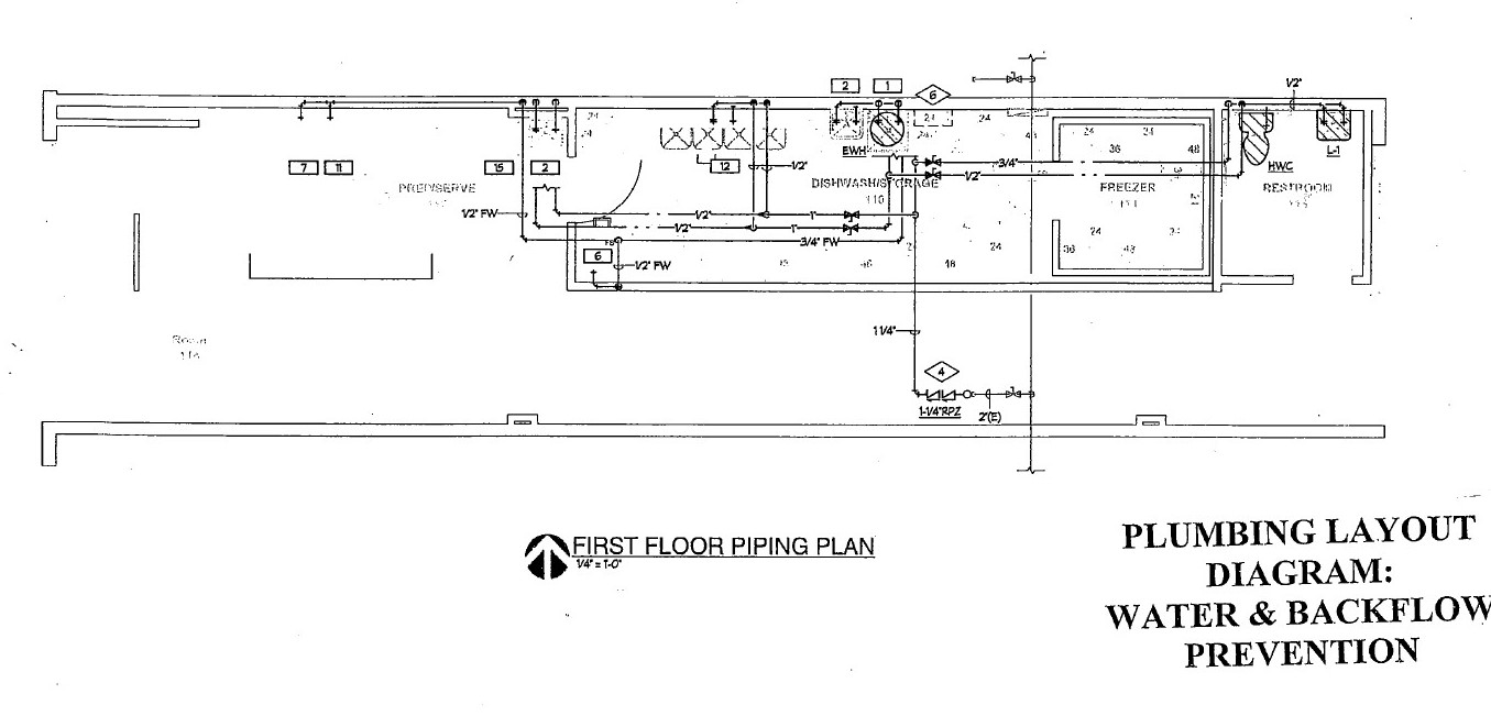
Plumbing layout diagram
- All Water Supply Service Lines (Domestic, Irrigation, Fireline) must be labeled and shown separately. Example: WSL = Water Service Line (or Domestic Line), FL = Fire Line, etc.
- Label each of the fixtures and show the points of connection from the service line to the fixture.
- Indicate the location, the make and model number of the backflow prevention device(s).
- Plans must be drawn to scale.
- On Remodel projects, notate on the plans which fixtures are existing or proposed. This can be done via a numbered Plan Note.
For more information about backflow prevention requirements or to seek approval for a proposed device, please contact the Environmental Program Coordinator at (812) 349-3633. Additional Program details, Informational Brochures, Standard Details, Approved Devices, Installation, Inspection, and Testing Requirements, and submission of the testing reports are available under the Backflow Prevention section of our website.
SAMPLE DIAGRAM:
NEW SERVICES & TAPS:
Waiver of Protest to Annexation:
Before a new development outside the corporate limits can receive City sanitary sewer service, the developer must sign a blanket waiver of protest to annexation for all property within the project area, in accordance with Indiana Administrative Code 36-9-22-2. No water meters will be set until the waiver has been signed. For further information, contact the City Legal Department (812-349-3427). Submit a copy of the recorded Waiver of Protest to Annexation document to the Project Coordinator - New Services at CBU.
Fixture count data:
To be submitted to the Project Coordinator - New Services to accurately size meters and service lines. The appropriate form(s) are available on our website.
Taps:
All taps on existing sewer and water mains owned by CBU must be made by CBU personnel. Please call the Project Coordinator - New Services at (812)349-3689 for information on taps and fees.
Service Lines and Meters:
Project Coordinator - New Services must size service lines and meters. Please provide an accurate fixture count for each building. At your request, information on fees will also be provided (812-349-3689).
Applications and Connection Fees:
All connection fees are to be paid in advance of installation of service and/or meter. Please call the Project Coordinator - New Services at (812)349-3689 for information on applications for service, and fee quotes. Fee information is available on our Taps, Service Installation, & Fees page.
SANITARY SEWER:
All projects connecting to the City of Bloomington Utilities Sanitary Sewer System must submit plans for review and approval by our Engineering staff. As part of the project review, please reference the items outlined in our Design Standard Manual and Project Review Guidelines. All sanitary sewer main extensions must complete the IDEM Sewer Construction Permit Application. Submit a completed application to our office for review and signature. For any projects requiring Pretreatment review, please refer to the PRETREATMENT section in our Design Standards Manual.
- Design Standards Manual – SEWER Section
- Design Standards Manual – PRETREATMENT Section
- Design Standards Manual – NEW SERVICES & TAP APPROVALS Section
- IDEM Permit Guide – Water & Sewer
- PRETREATMENT PROGRAM
- LIFT STATION SPECIFICATIONS
IDEM Sewer Construction Permit:
IDEM has informed us that ALL Sanitary sewer extensions, regardless of length, require an IDEM Sewer Construction Permit. If your plans include sanitary sewer, please provide us with a copy of your completed IDEM application form. Please be certain to include the Capacity Certification/Allocation Letter (Acceptance of Flow Form).
For all application & permit correspondence, please list the following cc contact information for CBU as follows:
City of Bloomington Utilities
Attention: Engineering Dept
P.O. Box 1216
Bloomington, IN 47402-1216
Email: [email protected]
Clean-outs:
Reference section 4.5.2.1.5.1 of the CBU Construction Specifications.
Grease Interceptor:
Refer to the PRETREATMENT section below.
C900 Pipe:
Wherever C900 pipe is used for sanitary sewer, all wyes shall be HARCO, sized for C900 on the run and SDR-35 on the branch. Transition from C900 to SDR-35 pipe shall be made by use of a HARCO C900 to SDR-35 Adapter.
Ductile Iron Pipe:
All DIP used for sanitary sewer shall have a ceramic epoxy lining, minimum thickness 40 mils and shall be Protecto 401. Wyes for DIP shall be HARCO DIP to SDR-35 Adapter Wyes.
Connection to an Existing Manhole:
When connecting a new pipe to an existing manhole, the manhole shall be core-drilled. Pipe shall be connected to the manhole by either a flexible boot KOR-N-SEAL 1 or 2 flexible connector or approved equal. Invert of the connection shall be no more than one foot higher than invert out for this structure. Table and trough shall be modified as necessary to direct the flow from the new pipe.
Slopes greater than 20.00%:
Concrete anchors shall be required for stabilization of any pipe having a slope greater than 20.00%. The pipe for the entire run shall be Class 350 DIP with a ceramic epoxy lining, minimum thickness 40 mils and shall be Protecto 401.
Force Mains & Wastewater Lift Stations:
Engineer is to submit calculations and lift station specifications for review. Indicate the ownership of the force main and/or lift station by line type.
Payment for Oversizing:
Section 13.4 of the CBU Rules, Regulations and Standards of Service states, “If, for the Utility’s future plans, a water or sewer line larger than the one required for the extension is needed, the Utility will pay for the increase in cost. This increase in cost will be determined as follows. The cost of pipe and appurtenances will be determined for the proposed line and for the line required by the Utility. The Utility will pay this difference in cost plus twenty percent (20%). In no case will the cost of the proposed line be less than the cost to install a 6 inch water line or an 8 inch sewer line.” Contact the Project Coordinator - New Services at 812-349-3689 for additional information.
PRETREATMENT PROGRAM:
Grease Interceptor:
An exterior grease interceptor must be provided if the building will house a Food Service Establishment as defined by Bloomington Municipal Code Chapter 10.17. Grease interceptors shall be sized according to the 2006 Uniform Plumbing Code Gravity Grease Interceptor Sizing Method (Table 10-3) or other sizing method that provides a minimum 30 minute hydraulic retention time. Precast concrete grease interceptors must be designed and constructed in accordance with the City of Bloomington Utilities Department’s Standard Grease Interceptor Detail (Detail #21). Plan submittals must include the location and calculated volume of the interceptor, CBU interceptor detail #21 or a pre-approved alternative interceptor detail, and the plumbing layout of all kitchen fixtures and “grease only” sewer lines, both interior and exterior. Wastewater from 3-bay sinks, pre-rinse sinks, mop sinks, hand sinks, and floor drains shall be discharged into the grease interceptor. Commercial dishwashers shall not be plumbed to the grease interceptor. The installation of new or the replacement of existing garbage disposal units in Food Service Establishments is prohibited. For more information about grease interceptor requirements or to seek approval for a proposed interceptor installation, please contact the Pretreatment Program Inspector at (812) 349-3934.
Plumbing Plan Requirements:
All Food Service Establishment (FSE) plans or Commercial developments within areas zoned for FSE’s must include these items before approval will be granted for Grease Interceptor installation. Sample diagrams are available on our website under the Pretreatment Program section.
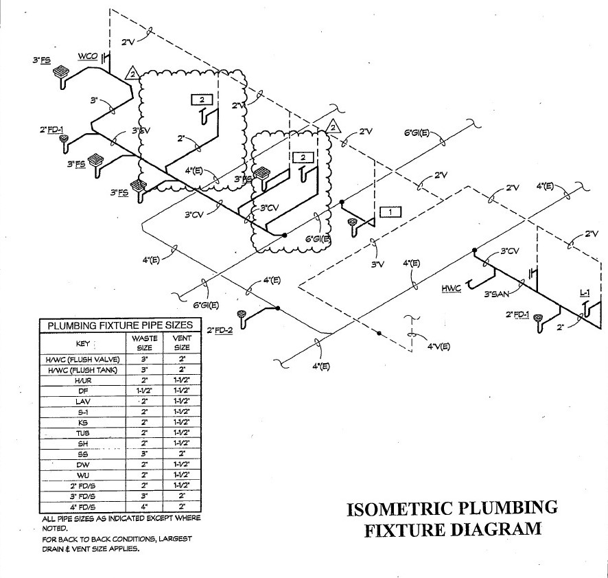
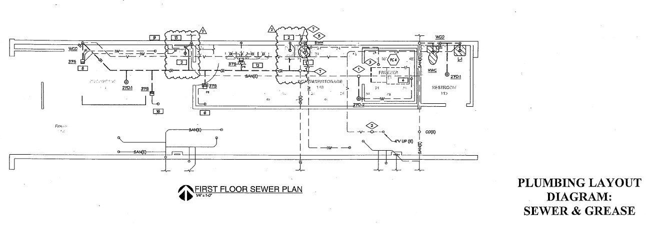
Plumbing Diagram (Internal Layout)
- All Water Supply Service Lines, Firelines, Sanitary Waste and Grease Waste lines must be labeled and shown separately. Example: WSL = Water Service Line (or Domestic Line), FL = Fire Line, SSL = Sanitary Sewer Line, GWL = Grease Waste Line.
- Label each of the fixtures, floor drains, cleanouts, vents, etc in their proper location. Include the fixture trap arm size and show the points of connection from the fixture to the proper waste line.
- Plans must be drawn to scale.
- On Remodel projects, notate on the plans which fixtures are existing or proposed. This can be done via a numbered Plan Note.
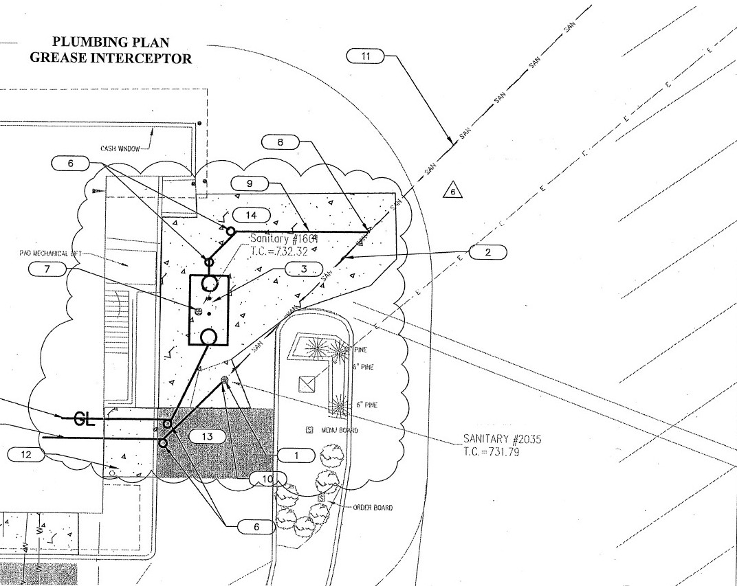
Grease Interceptor (External Plan Layout)
- Grease interceptor standard detail or specification sheet from the manufacturer (example: Proceptor unit).
- Type & Size of the grease interceptor unit
- Connection of the grease waste line into the GI unit
- Show where the GI unit will connect back into the existing lateral; or the new connection point on the City main.
- Include locations of the clean outs, vents, sampling ports, etc.
Oil-Water Separator:
If you are installing an Oil-Water Separator, please contact the Pretreatment Coordinator at (812)349-3946 or [email protected].
Product Manufacturing:
If you manufacture any product, complete the Wastewater User Survey (Manufacturing User / short form) and submit it to the Pretreatment Program Coordinator at [email protected].
Brewery / Distillery:
If your facility plans to manufacture alcohol, you will be included in our High Strength Surcharge Program. Please contact our Pretreatment Coordinator for more details at [email protected].
Industrial Pretreatment:
If you manufacture any product, complete the Wastewater User Survey (Industrial User / long form) and submit it to the Pretreatment Program Coordinator at [email protected]. Link: (long form)
PRETREATMENT SPECIFICATIONS:
Non-Concrete / Hydro-Mechanical Grease Interceptors:
| Manufacturer | Model | Flow Rate | Grease Retention |
| Schier | GB 250 | 100 GPM (minimum) | 1,895 Lbs / 277 gal |
| Schier | GB 500 | 100 GPM (minimum) | 3,048 Lbs / 510 gal |
| Schier | GB 1000 - Refer to their website: Schier Products | 100 GPM (minimum) | 5,495 Lbs / 1,000 gal |
Precast Concrete Grease Interceptors:
| Manufacturer | Size |
| Precast Solutions | 750 Gallon |
| Precast Solutions | 1000 Gallon |
| Precast Solutions | 1250 Gallon |
| Precast Solutions | 1500 Gallon |
| Precast Solutions | 2000 Gallon |
| Sexton Wilbert | 750 - 3000 Gallon |
Grease Proceptors:
Grease Traps: Automatic Grease Removal Devices
**These devices are only approved as replacement devices for EXISTING grease traps. No approvals will be granted on new installations.
| Brand | Model | Flow Rate | Grease Retention |
| Grease Guardian | GGX15 | 15 GPM | 30+ Lbs |
| Grease Guardian | GGX20 | 20 GPM | 40+ Lbs |
| Grease Guardian | GGX25 | 25 GPM | 50+ Lbs |
| Grease Guardian | GGX35 | 35 GPM | 70+ Lbs |
| Grease Guardian | GGX50 | 50 GPM | 100+ Lbs |
| Grease Guardian | GGX75-IS | 75 GPM | 150+ Lbs |
| Grease Guardian | GGX75-AST | 75 GPM | 150+ Lbs |
| Grease Guardian | GGX125-IS | 125 GPM | 250+ Lbs |
| Grease Guardian | GGX125-AST | 125 GPM | 250+ Lbs |
| Big Dipper | W-200-IS | 20 GPM | 47 Lbs |
| Big Dipper | W-250-IS | 25 GPM | 56.4 Lbs |
| Big Dipper | W-250-AST | 25 GPM | 73.29 Lbs |
| Big Dipper | W-350-IS | 35 GPM | 85.18 Lbs |
| Big Dipper | W-500-IS | 50 GPM | 108.4 Lbs |
| Big Dipper | W-750-IS | 75 GPM | 168.95 Lbs |
| Big Dipper | W-750-AST | 75 GPM | 211.11 Lbs |
| Big Dipper | W-1000-IS | 100 GPM | THIS MODEL IS NO LONGER AVAILABLE |
SAMPLE DIAGRAM(S):
STORMWATER:
All Stormwater projects are reviewed by our Engineering staff. As part of the project review, please reference the items outlined in our Design Standard Manual and Project Review Guidelines. A full Stormwater review will include the utility plan & profiles, a grading plan, the stormwater drainage report, and any associated Operation & Maintenance Manual or Facility Operation & Maintenance Plan for the BMP’s.
- NEW ITEM: Include a Summary Chart or Note on the Site Plan for the Total Pervious / Impervious Areas.
Stormwater Calculations:
For all projects, calculations which support pipe sizing and inlet location must be submitted for review. Stormwater structures shall be designed for the 10-year storm without surcharging and checked to insure that structures are protected from flooding during the 100-year storm.
The Drainage Report should include:
- Drainage Calculations (include a note or table in the summary section showing the total Impervious and Pervious surface areas for the ENTIRE SITE)
- Basin Maps (Pre & Post Development)
- Grading Plan
- BMP Structures & Details
Inlet Design:
Inlets shall be placed to limit runoff spread into the road as follows: local streets and cul-de-sacs shall be designed so that one clear 8.0’ travel lane is maintained during the 10-year storm; arterials and collectors shall be designed so that runoff does not reduce the clear travel lane to less than 8.0’ for any lane. Inlets in a sump condition shall be designed to prevent overtopping of the curb during the 100-year storm with all upstream inlets completely clogged.
Methodology:
Inlet design for projects where the entire drainage basin is less than 50 acres may use the Rational Method to determine the peak discharge. Projects where the entire drainage basin is greater than 50 acres must use a rainfall to runoff analysis and develop a hydrograph to determine the peak discharge. CBU uses HEC-HMS to perform rainfall/runoff analysis, and submitted calculations must be reproducible on this software.
Storm Sewer Profiles
Construction plan submittals are required to include storm sewer profiles. We suggest omitting the storm sewer structure data table to avoid confusion. Include all applicable data: structure type, casting type, length, slope, inverts, top of casting, pipe material, stationing, utility crossings, proposed grade line, and existing grade line on the profiles.
Operation & Maintenance Manual / Facility Operation & Maintenance Plan:
Submit the appropriate documentation for review for all BMP devices, structures, ponds, or facilities installed as part of the development. Upon approval, a signed copy must be submitted to CBU with the Owner/Developer’s signature. The manual is to include:
- Title Page with project name, location, date of preparation, and “prepared by” information.
- The Owner’s Acknowledgement of Maintenance Responsibility complete with their contact name & title, company name (if applicable), mailing address, signature, and date.
- Development information for pre-construction standards and post-construction maintenance standards for all of the water quality features on the property.
- List the Water Quality features on site including inspection frequency and associated directions.
- Show all BMP/Drainage Easement Dedication Areas
- Include a planting list for all required seeding mixtures.
- Detail or Exhibit of Outlet Control Structures and their locations.
- Copy of Inspection form provided to Owner.
- Right of Entry granted to CBU for inspection of the BMP features as needed.
- Sample form(s) are available for reference on our website.
Utility Plan Note/Chart - Onsite Pervious/Impervious Area:
Provide the total amount of impervious surface and pervious surface (in acres) within the Notes section on the utility plan sheet. This may be in the form of a sentence or chart (see example below).
| Total Impervious Area (in acres) | 3.06 acres |
|---|---|
| Total Pervious Area (in acres) | 1.80 acres |
| Total Site Area (in acres) | 4.86 acres |
MS4 / CSGP SWPPP:
MS4 – SWPPP Review:
Any project requiring a CSGP SWPPP review must submit a separate set of plans, the completed CBU Plan Review Application(for New Developments) if you have not already done so, and remit payment for the $85 SWPPP review fee to our office. Any questions regarding the requirements outlined below should be directed to the MS4 Coordinator at (812)349-3637 or [email protected].
*Preferred Method* for SWPPP Plan and Document Submission:
- When submitting construction plans to CBU for review of CSGP projects, please also submit an electronic copy (PDF) of the SWPPP to [email protected]. The requirements for CBU's plan review remain the same; you can find them outlined on this page. For City-owned CSGP projects, please copy me when you send the SWPPP to IDEM and the Monroe County SWCD for their review.
With your initial SWPPP submission, please also include a copy of the first page of the CSGP NOI. This will give me the project information I need to complete the review.
Also with your initial SWPPP submission, a review fee of $85 must be submitted to CBU in order for the SWPPP review process to begin. The $85 SWPPP review fee can be found in Title 10.21 of the Bloomington Municipal Code. The payment is ultimately the responsibility of the Project Site Owner. Payments can be made by cash, check, or credit card.
- Please address checks to 'City of Bloomington Utilities,' and mail to: City of Bloomington Utilities, Attention: MS4 Coordinator, 600 E Miller Drive, Bloomington, IN 47401.
LANDSCAPING / EASEMENTS / PLATS:
All projects must submit a Site & Utility Plan showing the easements (existing & proposed), a Landscape Plan, and a Final Plat (if required). For additional information, please reference the items outlined in our Design Standard Manual and Project Review Guidelines. All questions should be directed to our Land Acquisitions Coordinator at (812)349-3628.
- Design Standards Manual – LANDSCAPING / EASEMENTS / PLATS Section
Easements:
CBU permission to construct sanitary, water, or storm mains is contingent upon the grant of easement covering all public facilities for which approval is sought. This may be in the form of a Blanket Easement that covers all of the parcel(s) on which the facilities are located, or specific easements over and along those facilities. This shall include any facilities to be built on said parcel(s) in the future that extend beyond the initial phase of the development. The easements must be signed, recorded, and submitted to CBU before construction of said facilities commences. The following must be submitted to Project Coordinator – Land Acquisitions of the Utilities Engineering staff along with the blanket easement:
- Copy of the deed(s) for the parcel(s) on which the facilities are located
- Plan showing the public facilities and the parcel(s) covered by the blanket easement
- Signed and recorded easement document drafted in accordance with a format provided by the Project Coordinator - Land Acquisitions (812-349-3628).
Private Infrastructure Crossing Multiple Parcels:
If a private service line, sewer lateral, or drainage feature crosses multiple parcels that are currently, or will be, owned by more than one property owner, an easement will be required to cover those utilities. Contact our Project Coordinator – Land Acquisition at (812)349-3628 for further details.
Landscaping:
Please check the landscaping plan to verify that no tree or shrub is indicated within ten feet of any sanitary, storm, or water main to be taken over by CBU. Please incorporate a copy of the Landscaping Plan into the plan set showing the existing and proposed utilities, as well as, existing and proposed easements.
Structures:
No permanent structure shall be located within ten feet of any sanitary, storm, or water main owned or to be taken over by CBU. Please be sure to review your proposed utilities with the proposed easements. Remember that "trees and structures including, but not limited to, buildings, fences, retaining walls, signs, and light fixtures, shall not be located within the Sanitary and Waterline Easements".
Final Plat:
For all developments that require the submission or revision of a plat, please submit a RECORDED copy of the Final Plat to Utilities Engineering Staff for our records.